Autonomous UGV Development
Three-phase autonomous tracked vehicle: GPS waypoint navigation, encoder-based dead reckoning, and LiDAR localization with ROS2/Nav2.

Overview
This semester-long project developed a fully autonomous tracked ground vehicle (UGV) capable of navigating complex environments without human input. The platform progressed through three increasingly sophisticated autonomy phases: GPS-guided outdoor navigation, encoder-based indoor dead reckoning, and LiDAR-assisted localization using ROS2/Nav2.
The project required integration across every engineering discipline: mechanical design for the drivetrain and sensor mounts, embedded C++ for low-level motor control, and autonomy algorithm development for guidance, navigation, and control. Team 4 consisted of Ryan Hailey, Faizan Khan, Christina Render, and Pete Torres.
Platform Architecture
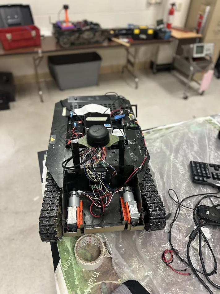
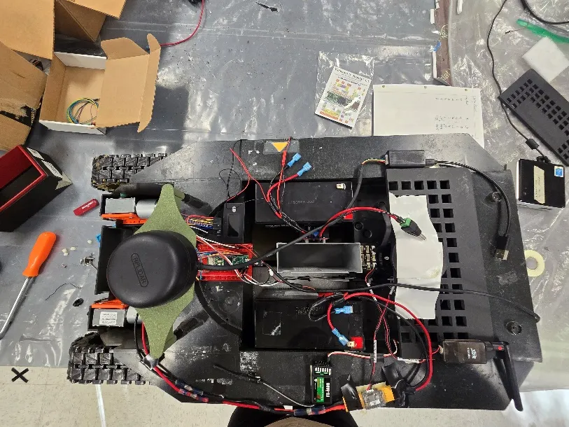
The vehicle is a skid-steer tracked platform driven by two independently controlled DC motors. The computing stack evolved over the semester from a single Pixhawk autopilot to a distributed architecture: a Teensy 4.1 for low-level embedded control and an Intel NUC (i5) for high-level guidance, navigation, and control.
Key hardware:
- Pixhawk Cube Black: autopilot for the GPS waypoint phase
- Teensy 4.1: embedded MCU for encoder reading, PPM to PWM conversion, and motor commands
- Intel NUC (i5): onboard computer running Simulink and ROS2 for GNC
- Slamtec RPLIDAR A2: 360 degree 2D LiDAR with 12 m range
- Dual-channel H-bridge: motor driver receiving PWM from the Teensy
- 12V sealed lead-acid batteries: separate power rails for compute and drivetrain
Phase 1: GPS Waypoint Navigation
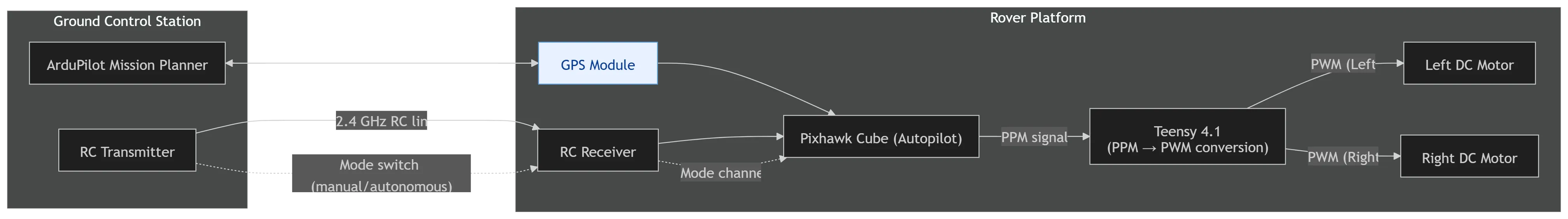
The first challenge was outdoor autonomous navigation using GPS. The Pixhawk Cube Black ran ArduRover firmware and received a preloaded sequence of GPS coordinates from ArduPilot Mission Planner over a 2.4 GHz RC link. It computed heading error and sent PPM signals to the Teensy, which translated them into left and right motor PWM commands.
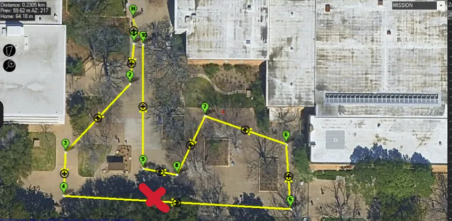
The waypoint challenge was completed on 02/25/2026 and witnessed by Dr. Huff. The platform successfully demonstrated autonomous waypoint following, navigating 4 of 10 planned waypoints before a mechanical failure ended the run. Dr. Huff confirmed the navigation system was fully functional. The intensive field testing that led to this confirmation drove significant mechanical redesign work across the drivetrain.
Phase 2: Indoor Dead Reckoning
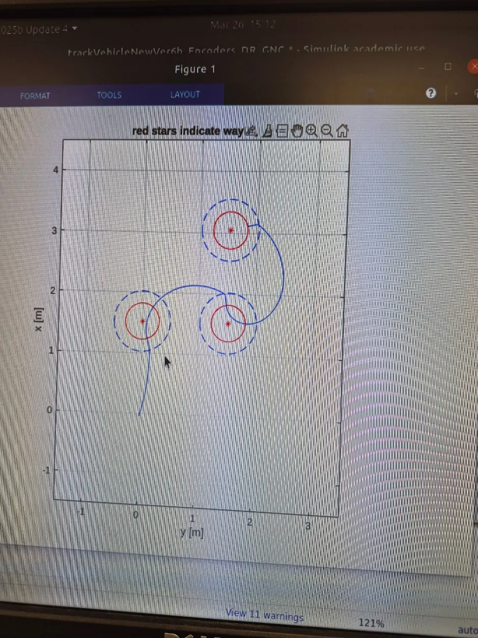
With GPS unavailable indoors, the platform transitioned to encoder-based dead reckoning. Quadrature encoders on each motor output shaft fed position and heading estimates into a differential-drive kinematic model. The Intel NUC ran a Simulink GNC block that closed the loop on position error, while the Teensy handled encoder reads and motor execution.
GNC Parameters
The GNC block used independent PID controllers for speed and heading. Key tuned parameters:
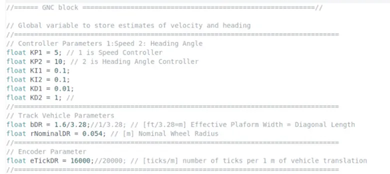
- Speed controller:
KP1 = 5,KI1 = 0.1,KD1 = 0.01 - Heading controller:
KP2 = 10,KI2 = 0.1,KD2 = 1 - Effective platform width:
bDR = 1.6/3.28 m(diagonal length) - Encoder ticks per meter:
eTickDR = 16000 - Feed-forward trim:
leftMotorFFTrim = 0.93,rightMotorFFTrim = 1.08
The motor trim values were determined empirically. The two motors had slightly different responses at the same PWM command, so per-motor feed-forward compensation was added to keep the vehicle tracking straight.
Dead reckoning worked well for short missions. Longer runs revealed drift accumulation inherent to skid-steer platforms, where ground slip and motor asymmetry compound into heading error over time. This motivated the move to LiDAR-based correction in the final phase.
Phase 3: LiDAR Localization
The final phase fused encoder odometry with a Slamtec RPLIDAR A2 to correct drift in real time. A custom LiDAR stand was designed in SolidWorks to raise the sensor above the tank body so the vehicle itself would not appear in the scan data. The stand mounted near the front of the platform, requiring a fixed positional offset to be applied during localization.
Simulink Scan-Matching
Two Simulink models were developed using the ROS toolbox to record and match LiDAR scans:
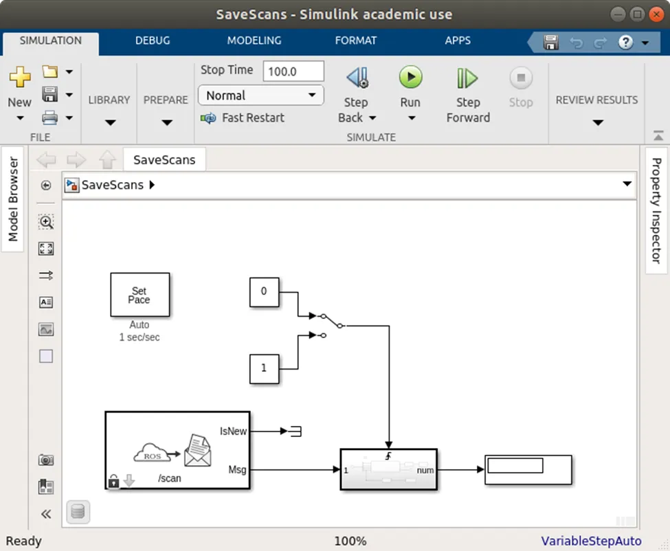
- SaveScans: triggered manually to record reference scans of the environment, saving
scan_angles.matandscan_ranges.matto the MATLAB workspace - MatchScan: compared live scans against the reference map using scan-line matching; an initial pose from odometry seeded the matcher, and an Extended Kalman Filter fused the corrected pose with covariance estimates
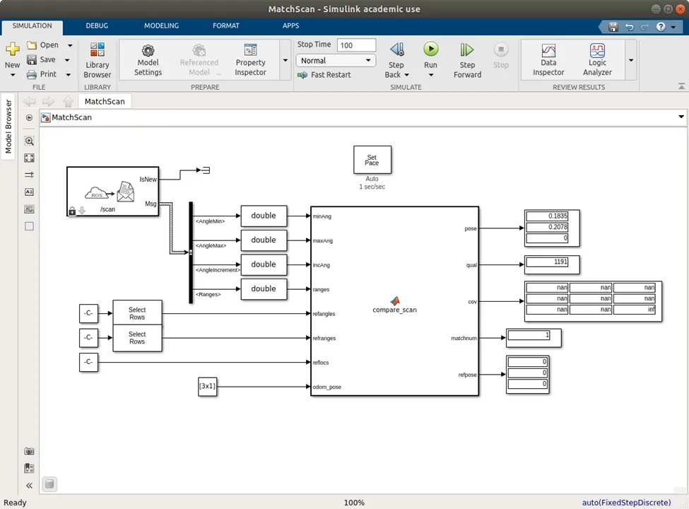
This approach provided valuable insight into the scan-matching and EKF fusion pipeline. Intermittent NaN values in the raw scan data highlighted the importance of data validation upstream of any state estimator, and led the team toward the more robust ROS2 toolchain.
ROS2/Nav2 Implementation
Near the end of the semester, the team transitioned to a ROS2/Nav2 stack, which produced significantly stronger localization performance:
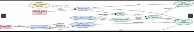
The Nav2 stack included:
- SLAM Toolbox: map building and scan matching from the RPLIDAR A2
- AMCL (Adaptive Monte Carlo Localization): particle filter-based position correction against a known map
- Nav2 Global + Local Planners: path planning and obstacle avoidance
- Waypoint Follower: sequenced mission execution
teensy_serial_bridge: custom ROS2 node translating Nav2cmd_velmessages into serial motor commands for the Teensy
This configuration delivered the strongest autonomous navigation results of the semester, completing multi-waypoint runs with reliable localization.
Mechanical Design
The drivetrain interface, connecting the motor D-shaft to the wheel assembly, was the most mechanically demanding component. Custom 3D-printed couplers and axles were designed in SolidWorks and iterated multiple times throughout the semester. Print orientation proved to be the key design variable: parts printed with layer lines aligned to the primary load path performed significantly better than those printed perpendicular to it.
Each mechanical iteration informed the next. Shaft and coupler geometry was refined, print orientation was corrected, and motor mounts were reinforced based on real-world loading observed during field testing.
Additional custom parts included an H-bridge mounting plate for the motor driver, a NUC housing placed centrally to improve center-of-gravity balance, and the elevated LiDAR stand.
Results
| Phase | Outcome |
|---|---|
| GPS Outdoor Waypoint Navigation | Demonstrated successfully; navigation confirmed by Dr. Huff |
| Indoor Dead Reckoning | Completed with solid short-range accuracy |
| LiDAR Localization (Simulink/EKF) | Revealed key data validation requirements; informed ROS2 pivot |
| LiDAR Localization (ROS2/Nav2) | Strongest results of the semester; reliable multi-waypoint runs |
Key takeaways:
- Print orientation governs FDM part strength under shear as much as material choice does
- Separate motor and compute power rails prevent current transients from disrupting the onboard computer
- Upstream data validation is critical before feeding sensor data into any state estimator
- Dead reckoning on skid-steer platforms requires empirical tuning of geometry and trim parameters, as analytical values alone are rarely sufficient